So the question “Is it possible to bit-bang a 6502 processor with a Propeller to make it work at 1MHz?” has been answered, and – as expected – the answer is YES!
After about 2 1/2 years of designing and coding (on and off — I could have done it faster if I could have worked on it full-time), Propeddle finally ran the first bytes of sample code by using the PASM bitbang code last Saturday, the 29th of June 2013.
One cog of the Propeller clocks the 6502, controls the RAM chip and controls the signals (IRQ, NMI, RESET…) and does this at 1MHz, so it has to do all of this in about 17 Propeller instructions per 6502 clock cycle.
A second cog “looks over the first cog’s shoulder” and checks when it accesses a predefined memory area in the 6502’s 64KB of address space. When it does, it quickly turns the RAM chip off and reads or writes a byte from the Propeller hub memory from/to the 6502 data bus. It has just enough time to do this, in 18 instructions (most of which are conditional and some of which are branched over)
A third cog also keeps an eye on the other cogs and logs every clock cycle to the Propeller’s hub memory so it’s possible to see a trace of what the 6502 did during every clock cycle. This Trace cog is a 13 instruction loop.
The first program simply increases a byte somewhere in the RAM chip and loops around. Of course it’s easy to do this on one of the locations in the Propeller hub too.
17 + 18 + 13 Assembler instructions doesn’t seem like much, but these three cogs (and more cogs in the future) have to cooperate very closely: timing is extremely critical. And the Propeller doesn’t have any debugging facilities and there are no simulators or emulators that worked well enough. I had to review the code countless times and recalculate the timings of each instruction just as often. And whenever I found a mistake in the first cog (the control cog), I had to scrap and rewrite the code for all the other cogs.
I’m excited that things are finally coming together, but I’m not there yet. I have some code to download bytes into the RAM chip by letting the 6502 execute dummy instructions while the Propeller accesses the memory, which still has to be tested. This can be used to simulate read-only memory in the RAM chip. Another cog whose code I haven’t tested yet, will keep the 6502 from writing to specific areas of the RAM, which effectively turns it into ROM. These two bits of software are next on my TO-DO list.
After that, it will be necessary to add some hardware emulation code to the project. Emulating a text video screen is trivial and I’ve pretty much already done that. I’ll probably add a video driver and keyboard driver, and start work on a driver for the serial port.
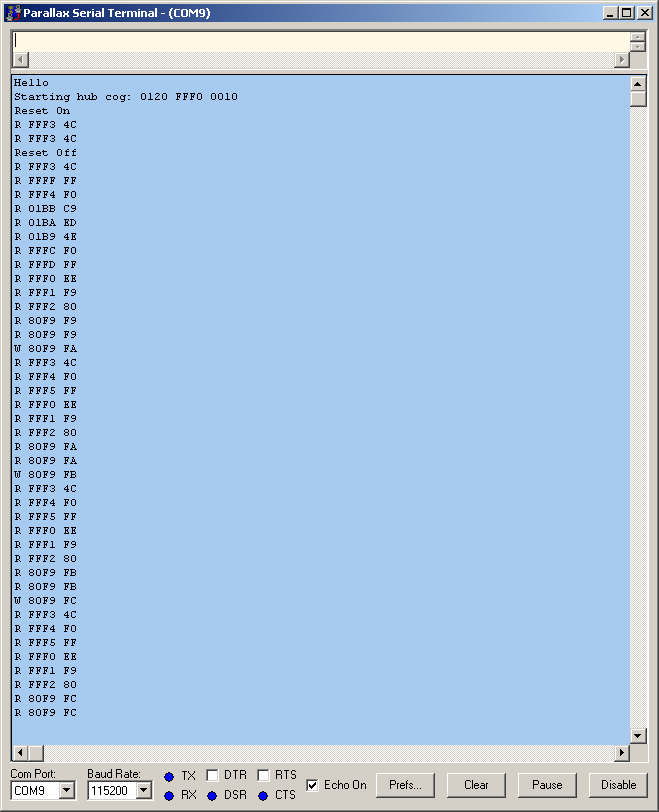
The screenshot shows one of the first runs at 1MHz. You can see how the code first activates the Reset line, then generates two clock cycles (that’s how long Reset needs to be kept active) and then executes 40 more clock cycles. The reset itself takes 6 cycles just like the datasheet says, and then the 6502 picks up the reset vector from $FFFC and $FFFD. The memory from $F000 to FFFF is “mapped to the hub” at $F000 so that’s where the reset vector points to. The program consists of the following instructions:
F000: EE F9 80 inc ($80F9)
F003 4C 00 F0 jmp $F000
Watch as it picks up the value of $80F9 (twice, because 6502 🙂 ), then writes the increased value back, then jumps back to $F000 to do it again.
*There’s just one more problem: All of this runs fine at 88 Propeller cycles per 6502 cycle (0.9MHz clock), but it should be possible to run it at 80 cycles and it doesn’t. This means there is a subtle timing problem at the end of Phi2 or the beginning of Phi1. I’ll have to set up my Logic Analyzer to find out what’s going on.
===Jac