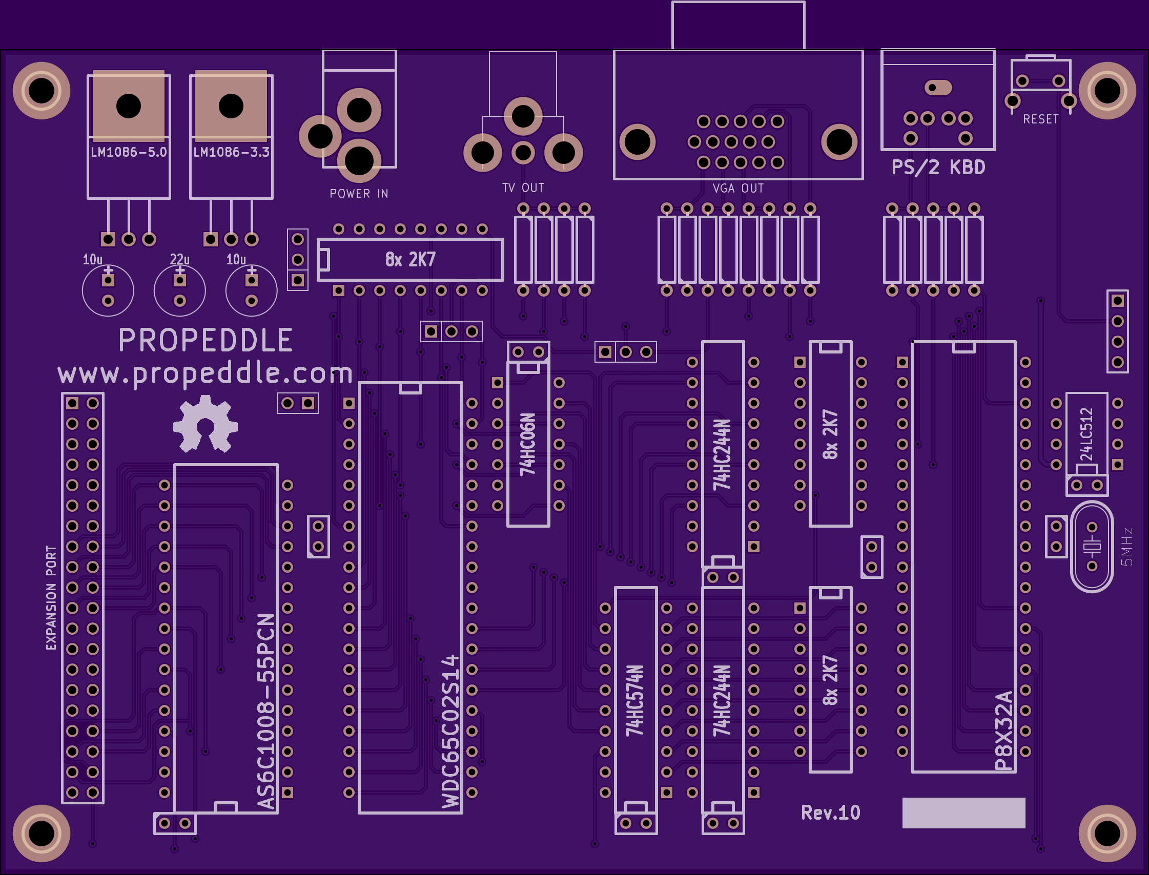
As I mentioned before, I’ve been working on a version of the Propeddle kit that has everything included: Not just the 65*02, memory and glue logic, but also the Propeller (and it surrounding hardware), and the connectors. Once I learned how KiCad works, this wasn’t very difficult, though I think KiCad could use some improvements when it comes to moving parts and traces at the same time. The result is a PCB that’s slightly smaller than a 160x100mm EuroCard, so it should fit in many standard enclosures.As you may notice, I made a few improvements to the design:
- I used one of the old “Reserved” outputs from the octal D-flipflop to control the Bus Enable (BE) on the WDC 65C02, and renamed the other one to “SETUP”. This will make is possible in the future to communicate with peripherals on the expansion bus via the data bus without a “detour” through the 6502. That way, the Propeller can set the address(es) at which the hardware should be active.
- The diodes on the control bus (~NMI, ~IRQ, ~RESET, RDY, ~SO and the new BE) were replaced by a 74HC06 open-drain hex inverter. I did this for three reasons: One, it’s easier to solder a socket and a chip than it is to solder six diodes, and there won’t be much danger of mounting any diodes the wrong way around; Two, the chip and socket are actually cheaper than the six diodes; and, last but not least: the inverters make it easier for multiple cogs in the Propeller to work together, and it may be possible to speed up the software a little. I’ll further explain this later.
- I used resistor packs (a.k.a. resistor arrays or resistor networks) for the pull-ups on the control bus, and for the 5V to 3.3V protection of the Propeller. The latter are only necessary if you want to run the 6502 part of the system at 5V, but I just noticed in the old kit that soldering all those 20+ resistors would get pretty boring. Plus, it took a lot of time to bend the legs of those resistors so I decided to put all the resistors flat on the board now I have a little more space.
- I added the Propeller, EEPROM and crystal to the design. There’s also a header for a Propeller Plug and a reset button.
- I added a 5V/3.3V, 1.5A power supply.
- I added a cinch (RCA) connector for TV-out, a VGA-connector and a PS/2 connector. I put all the connectors (except the Propeller plug header) on one edge of the board to keep it neat: I don’t like how some small single-board computers (you know the ones I’m talking about) have connectors on all sides. They get really messy when they’re all plugged in.
Unfortunately even though I don’t even have the boards back from OSHPark, I already found some problems:
- I forgot to let KiCad print the component values for the resistors and jumpers on the board
- The PS/2 keyboard connector had a slot as a hole for the shield ground; this is not supported so I’ll have to change the footprint and drill a hole in my prototype boards
There’s some more not-so-good news for those of you who already own a Propeddle: I figured the inverted control bus pins were so important that they were worth putting them in, even if I have to change the software and then that software won’t work with the old boards anymore. I also decided that it wouldn’t matter if I also made the order of the control bus pins different if I would have to change the software and make it not backwards compatible. This way I could make it a lot easier for myself to route the PCB. The pins on the expansion port were also reorganized, so any future expansion boards won’t work with older versions of the Propeddle PCB. To compensate for all this, I will give the current owners of the old PCB’s (I know who you are) a nice discount on the new kit when it’s ready.
I’m considering removing the VGA connector. The VGA output is already handicapped (pretty much only monochrome output is possible or maybe 7 colors but that would require some programming) and uses a lot of resistors which I already mentioned aren’t much fun to solder. Also it takes up a lot of space on the edge of the board, which I would prefer to use for e.g. a serial port. But most of all, for some 6502 based systems that I would like to emulate such as the Atari 2600, the Commodore 64 and the Nintendo, one Propeller just isn’t enough to do all the work for the video and the other hardware. So I’m thinking of reorganizing the schematic a little and adding an optional second Propeller in parallel to the first one, and letting the second Propeller take care of fancier video systems and mass storage (MicroSD). But all this can definitely be regarded as Feature Creep, so it won’t be implemented for now.
===Jac