A while ago, I announced here that I was considering making a wire-wrap version of Propeddle. The article is gone now: I kinda gave up on it because I was busy with lots of other things. But in the last few weeks, I started thinking about the idea again while I was working on the Kicad schematics, and decided to go ahead and make a wire-wrap version of Propeddle, based on the Parallax Propeller USB Proto Board, and the Human Interface Board.

I’ve never really done a wire-wrap project before, though I’ve been thinking of doing one for a while. When I look at pictures of Cray or DEC computers or projects such as Big Mess O’Wires, all those wires look like such a mess but you just know that the entire machine still works because whoever designed and built it, cared enough to make sure that everything is connected correctly.
Dennis Ferron’s Prop-6502 project, on which Propeddle is based, was built on a Parallax USB Proto Board (#32212) which has the Propeller chip right in the middle of the board. But Propeddle has more chips (and bigger ones), so there’s no way to use that board for Propeddle unless I dead-bug at least one chip. But a year or two ago, Parallax came out with the Propeller USB Project Board (#32810) which is a much improved version of the USB proto board:
- It doesn’t have the PS/2 connectors but it does have a place to mount a VGA connector
- It has a place to mount a MicroSD card reader which I may add to Propeddle later
- It has a place to mount a barrel connector socket for a power supply
- It has a place where you can solder a header to mount a QuickStart-compatible daughterboard
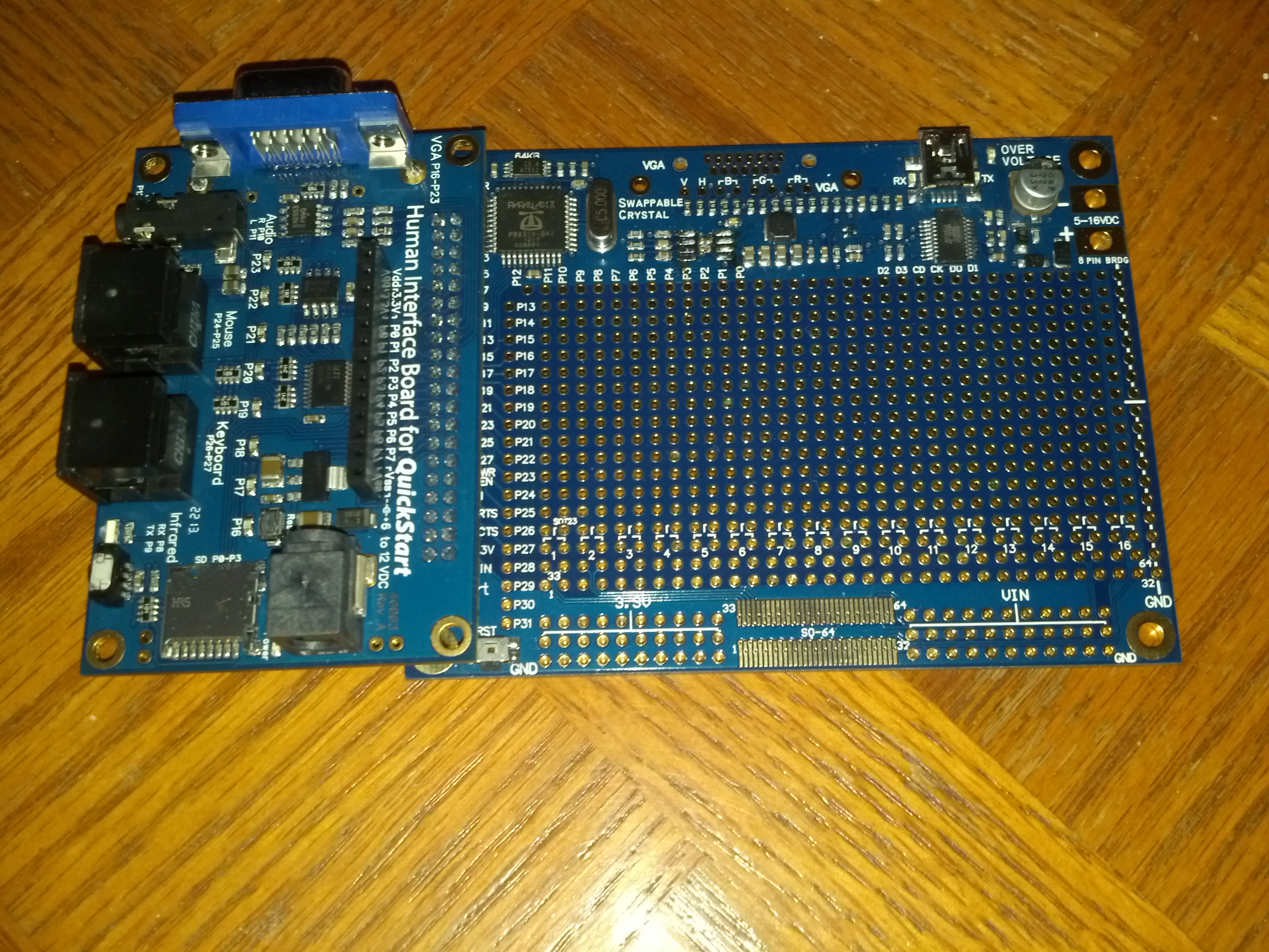
- Most importantly: all components are at the edge of the board, leaving a huge amount of space for lots of parts!

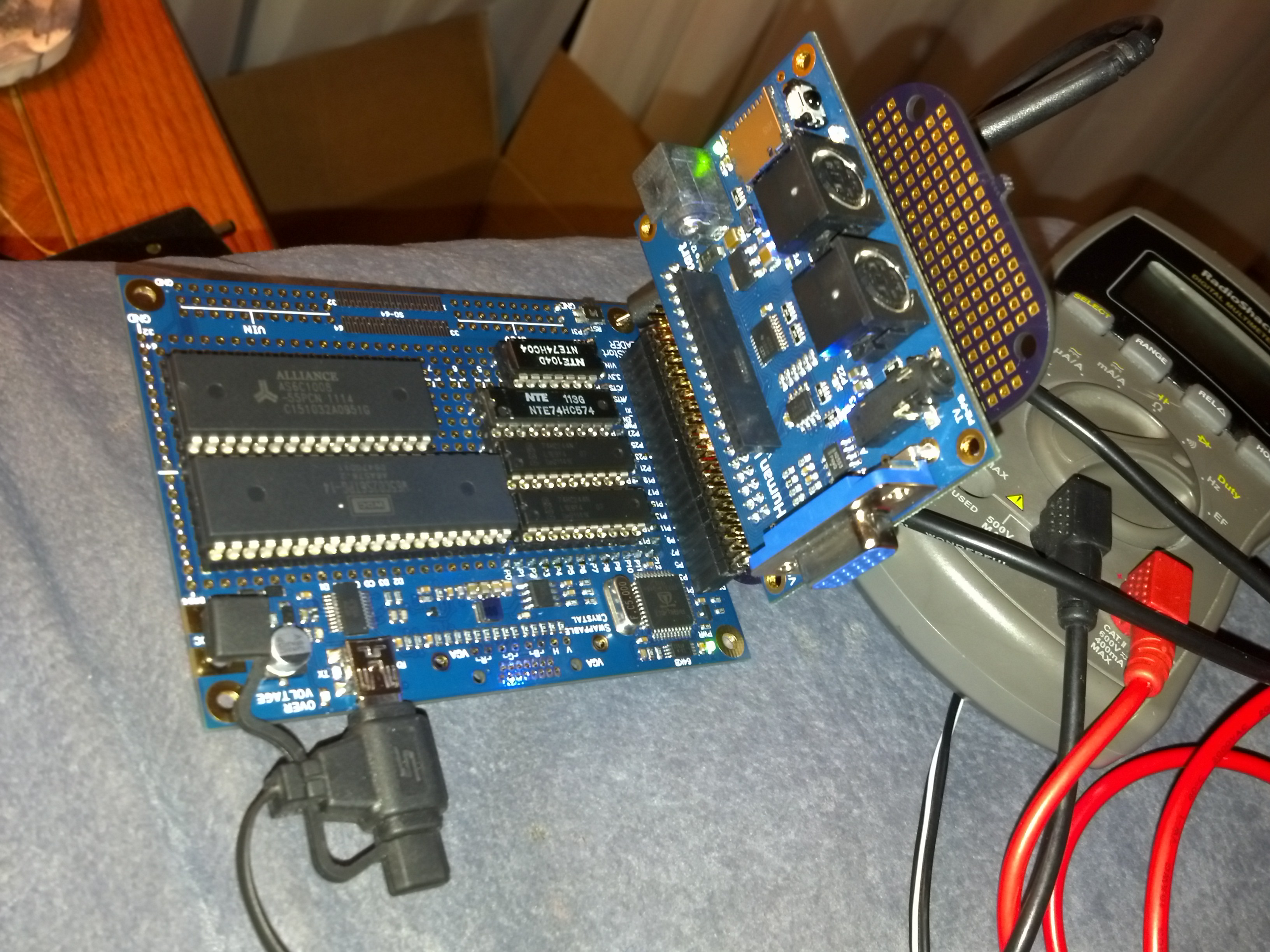
As you can see, all the parts of the Propeddle project fit nicely on the board, with even a little bit of space to spare! I mounted a power socket, a VGA plug and a MicroSD reader on this board because I thought I was going to use them. I also got a PS/2 mini-din socket and an RCA socket for TV-video out but I never soldered those to the board: I found out that Parallax makes the Human Interface Board (#40003) which is perfect (well, almost perfect) for my project:
- It has two mini-din sockets for PS/2 keyboard and mouse
- It has a power socket and 5V power supply which is needed to feed keyboard and mouse, and also powers the QuickStart or USB Proto Board
- It has a MicroSD, VGA connector and TV/audio connectors already on-board (no additional purchase necessary!)
- It has a couple of LEDs on board that come in useful for debugging
- It also has an IR LED and receiver/demodulator but I won’t be using that
The USB Proto Board lets you solder a header (unfortunately not available from Parallax) to connect the Human Interface Board, and its orientation is reversed from the one on the QuickStart board, so that it sticks out from the side when you plug it in normally, instead of covering the board like it does with the QuickStart. That may not be so great if you want to make your project as compact as possible, but it does give you full access to your project in case you want to poke a multimeter or oscilloscope or logic analyzer into it. Awesome!
The thing that makes the Human Interface Board not perfect for the Propeddle project is that all the devices on the Human Interface Board are hard-wired to the Propeller pins in the same way as the original Propeller Demo board assigned them. But while I kept the PS/2 keyboard on the standard pins P26/P27, this wasn’t possible for the TV and VGA outputs, because the address bus and databus of the 6502 circuit definitely need to be on pins P0..P15 to minimize the number of PASM instructions to work with them.
The solution to this is a small board that I made from a piece of perfboard that I once got as a freebie from OSH Park. I soldered a female and a (right-angle) male header, and two extra headers in between. The two headers in the middle are connected to the male and female headers on the outside by soldered wires, but there are no fixed connections between the middle headers. The middle headers are meant to connect devices on the Human Interface Board to any pins on the QuickStart or USB Project Board, by using wire-wrap wire.
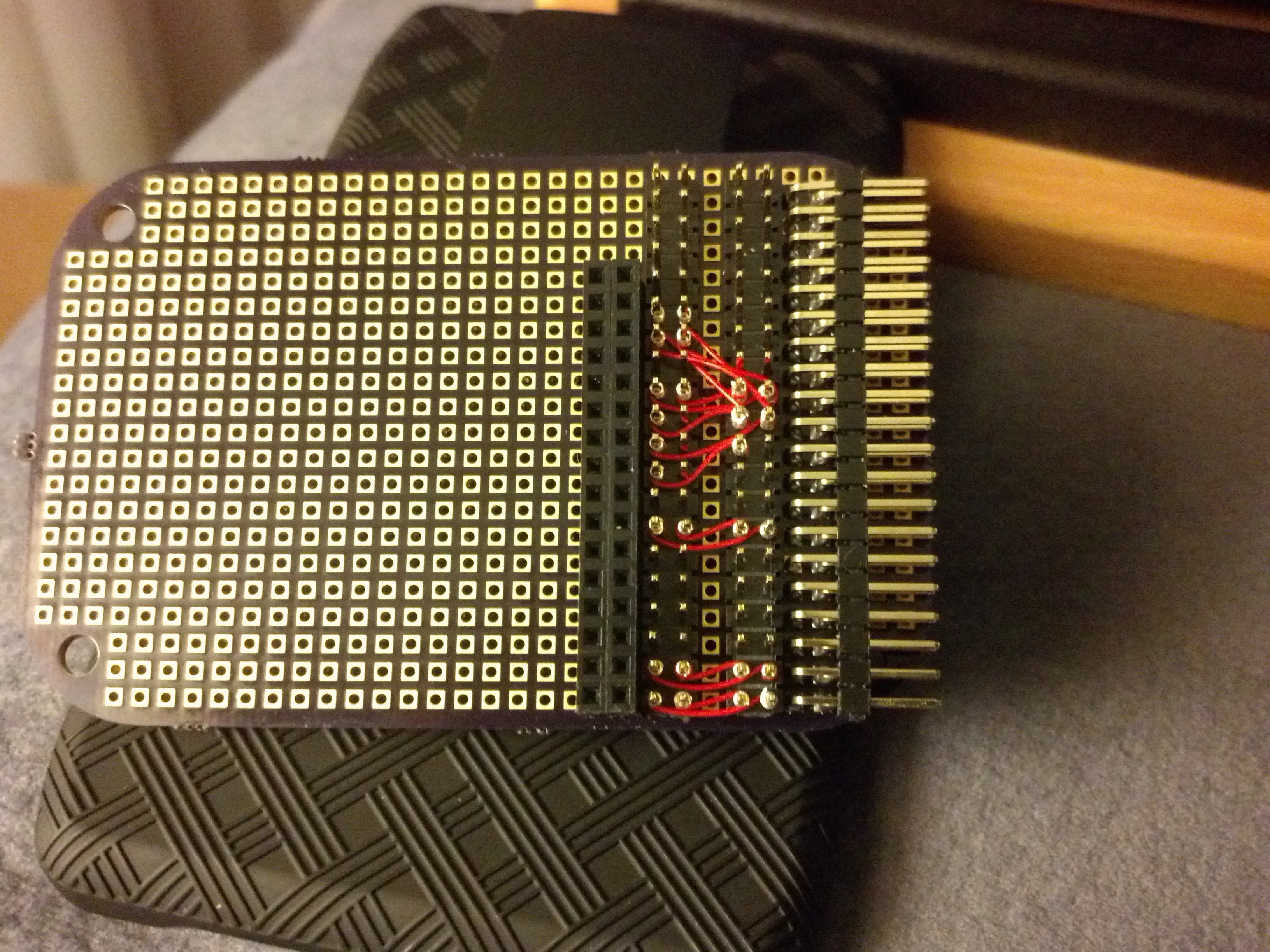
As you can see, I didn’t have a 40-pin female header so I used two 16-pin single-row headers: I’m not using P0..P7 on the Human Interface Board anyway.
Anyway, back to the Propeddle wire-wrap. One improvement that I wanted to make to the schematic was to put inverters on the signals. The reason is that the Propeller connects the outputs of each cog together via an OR-port, and I wanted to make it possible for any cog to activate the ~IRQ, ~NMI, ~RESET or ~SO lines, or deactivate the RDY or BE lines. So I added a hex open-collector inverter chip to the schematic, and I wanted to test this idea before I put it in production. It would be necessary to make the software incompatible with the old hardware (though compatibility may return once I switch back to the C language, by way of conditional compilation) but I figured that the added flexibility would make the design so much more flexible that it was worth it.
Once I finished the wire-wrap, I noticed there was a problem. Sometimes the board simply didn’t want to power up, no matter how much I jiggled with the USB plug or the power plug. On closer inspection, I saw what the problem was:
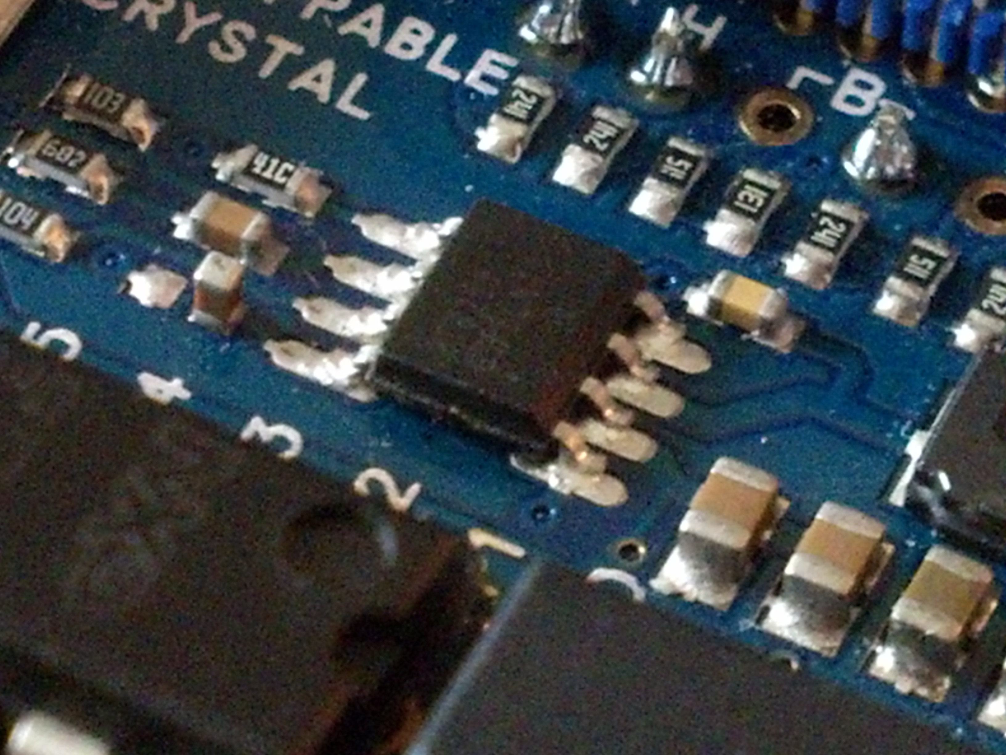
When I got the USB Project Board, I noticed there was a tiny capacitor that was standing up instead of lying down. But apparently the board worked fine, so I left it as it was and finished the wire wrap (I only had one USB Project board anyway so I didn’t have much choice). But now I noticed that the four pins on the right side of the power chip didn’t appear to be soldered at all. No wonder the thing was so flaky!
Alright, that shouldn’t be too hard to fix, right? Just put a sharp tip on the soldering iron, skip the coffee for a steadier hand, and make sure I have solder wick, just in case.
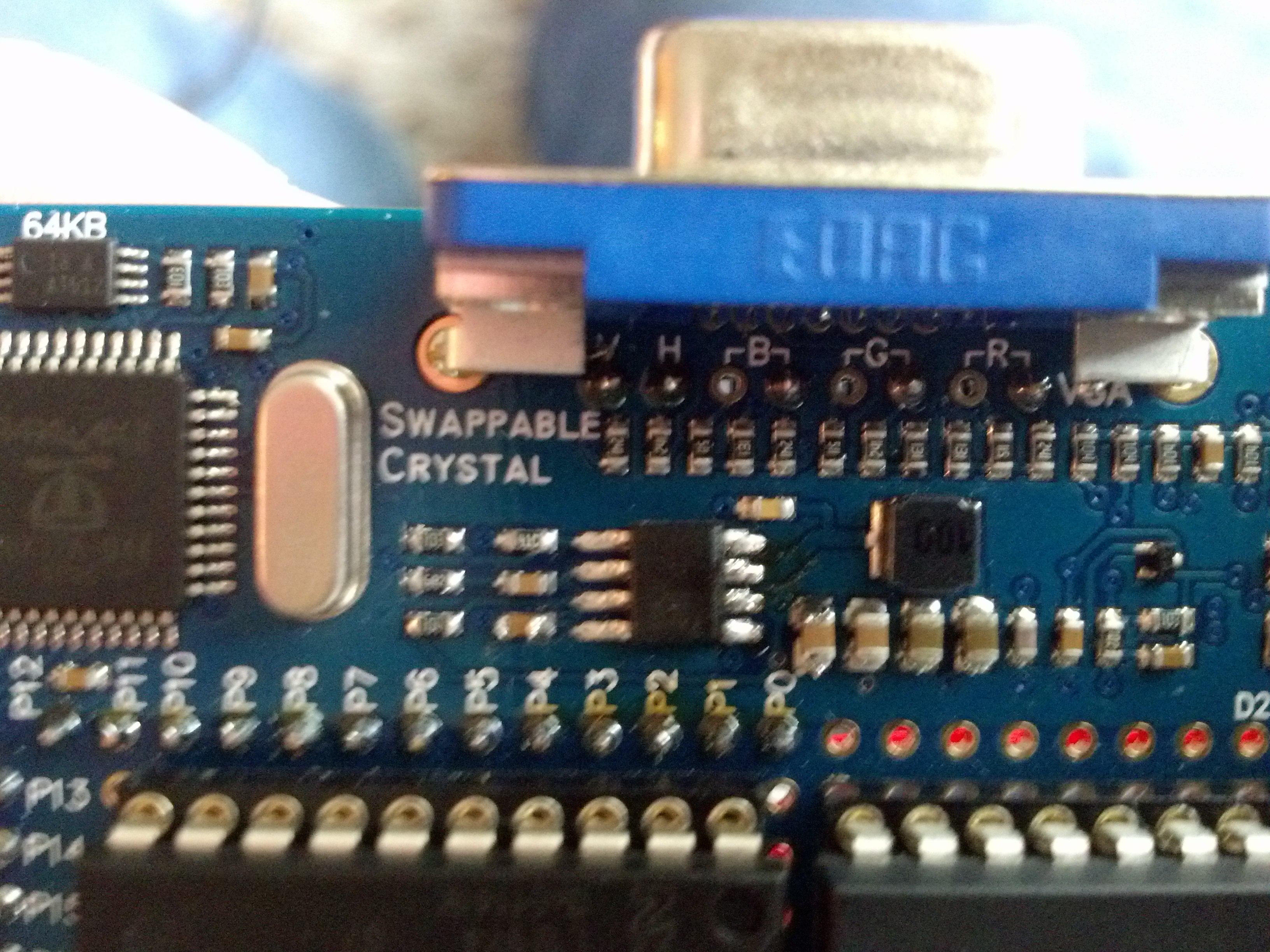
Unfortunately, once I soldered the chip and capacitor down, the board didn’t work at all anymore. I tried to take an identical chip off another board and it didn’t work either. Bummer! So two project boards wasted (this one and the one that donated the chip), plus almost a whole roll of Kynar wire, and a bunch of single-row headers and expensive wire-wrap sockets. Sure, I could have tried to take the wires off and then try to desolder the sockets, but that’s just not easy with wire-wrap sockets. Maybe later on I’ll get two of those chips and make both boards work again.
So I started the same wire-wrap on a new board. I guess it’s good that I had three of those things! The bottom of the board is shown near the top of this post.
I made the software (still little more than a test program) work with the new hardware with the inverters. You can find it on GitHub. And guess what:
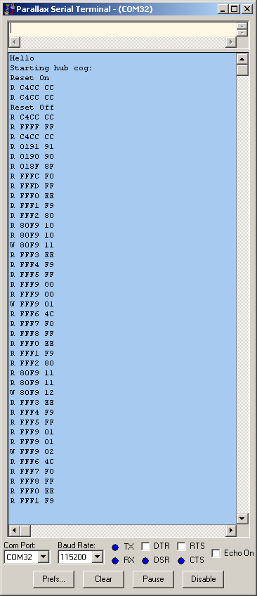
The old circuit boards didn’t let me run the Propeddle project at the full 1MHz that it was designed for. I still haven’t figured out why. But to my surprise, the wire-wrap version of Propeddle does run at up to 1MHz. I have to admit, the Trace cog apparently has some trouble at full speed so it shows the wrong information (and the screenshot shown above was generated at 909kHz for that reason) but clearly the 6502 is doing what it’s supposed to do even if the Trace cog isn’t picking up the correct values, probably because of some subtle timing problem that should be fixable.
There are some ways to tweak the software to make it run faster. For example, instead of switching the clock on and off with PASM instructions, I can run a timer that generates the clock. Also, I may be able to eliminate an instruction or two from the main Control loop by not testing the Signals for zero (this is used to let a Spin program terminate the main loop, but a PASM program can do this by holding the clock high so it’s kinda redundant). Furthermore, because of the inverters and the fact that any cog (running a PASM program) can now “jump in” and activate a signal, it may even be unnecessary to let the Control cog get the signals from the hub: it can just “let the other cogs know” somehow that it’s going to latch the signals, and then do it, without the need for a lengthy hub instruction.
But first, I’m going to build a Rev. 11 Propeddle on a Rev. 10 PCB. I got three Rev. 10 PCB’s from OSH Park this week and they’re mostly the same as Rev.11, except Rev. 10 has a couple of mistakes in the silk screen and drill files that have already been fixed, and one or two small differences in the schematic which I can fix while I put the parts on. The parts are on their way from Mouser and will arrive some time this week. If everything works (and fits) as expected, I will order a small run of the kit, and I’ll put it up on Tindie.
I still have a number of parts from the old kits in stock, so I can probably give early buyers a nice discount in return for showing their trust and buying the hardware while the software is not “ready” yet. The Rev.11 kit will include the circuit board, the WDC65C02, the Propeller and all the electronics to make a Propeddle. You will only need to provide a computer with a USB port that can run the Propeller tool (or the SimpleIDE program), and probably a DC power supply that can provide something like 9Volts, 1Amp. A PS/2 keyboard and a VGA or TV monitor will be highly recommended.
More information will follow soon!
===Jac