I’ve built probably about a dozen prototypes of the various versions of Propeddle over the last three years, but this is the first time that Propeddle has come alive by itself, on its own circuit board, without any assisting hardware (other than the power supply and the Propeller Plug). And I found and fixed the bug that I was talking about in the previous post, in the trace cog.
I already had the Rev.10 PCB from OSHPark, but it needed some work. For example, I forgot to put the values of the resistors and jumpers, the PS/2 keyboard connector was supposed to have a slot, but those aren’t supported by OSHPark; there also are some holes missing on the PS/2 connector. I already knew about most of the mistakes, so I started on a Revision 11 which will probably end up being the release version of the hardware.
Besides fixing the mistakes on the Rev. 10 board, I also wanted to do one last prototype build. Call it a dress rehearsal for the release, if you will. I wanted to figure out what the parts cost and make sure that the electronics work, now that the Propeller and everything are part of the schematic (remember: before this, Propeddle was a plugin board for the Propeller Platform so you needed extra hardware to make it work).
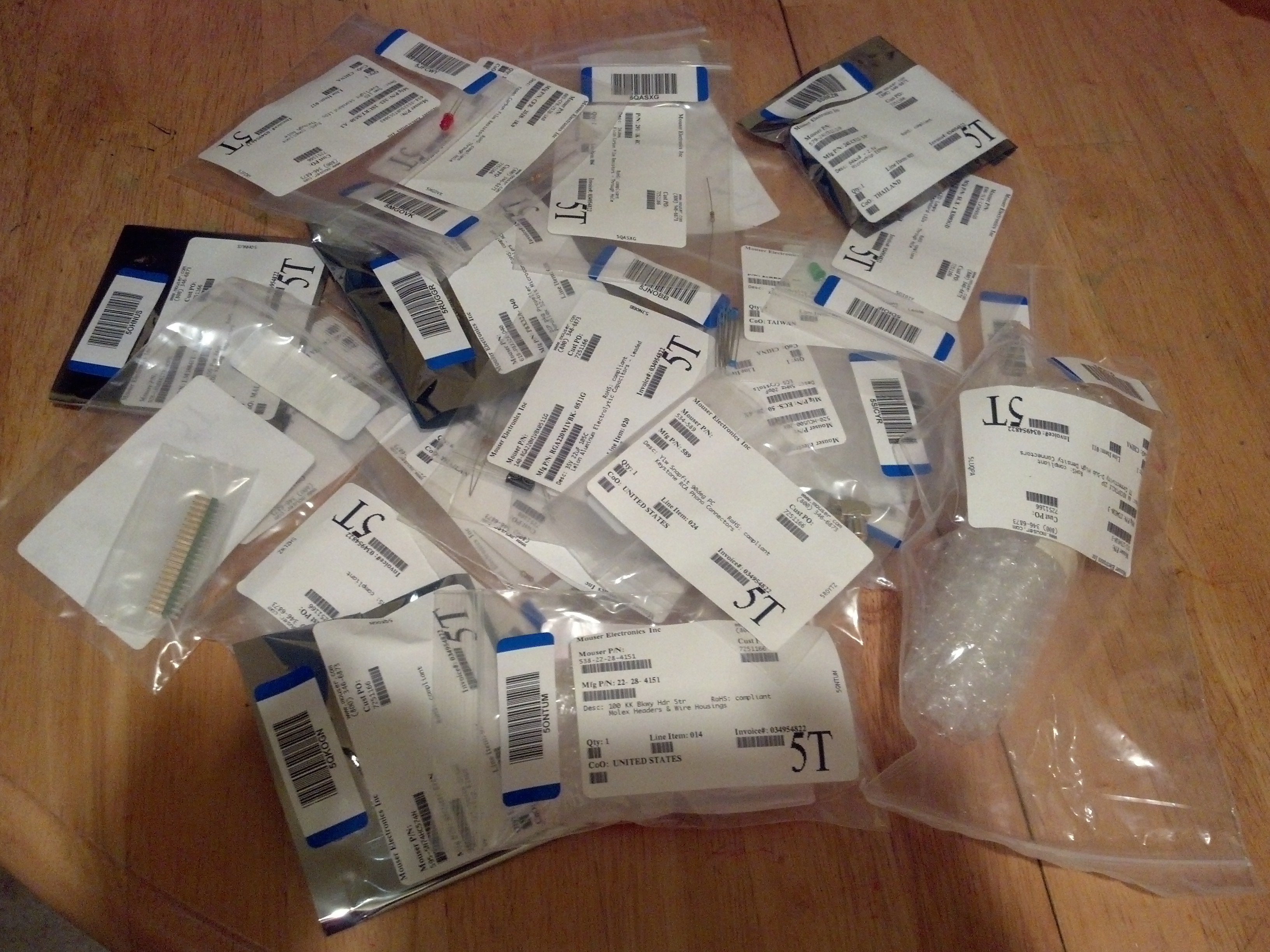
The box I got from Mouser was bigger than I expected, and had big stickers “FRAGILE” all over it. I wondered what that was all about; I wouldn’t think any of the parts in Propeddle would deserve that label. But when I took all the parts out of their baggies, I understood: those breakaway strips of headers have a way of breaking during transport (especially when they’re long), and on connectors with long pins that are close together (like, let’s say, a VGA socket) have a way of getting bent out of shape when they’re treated roughly. So I appreciated how those parts were extra carefully wrapped.
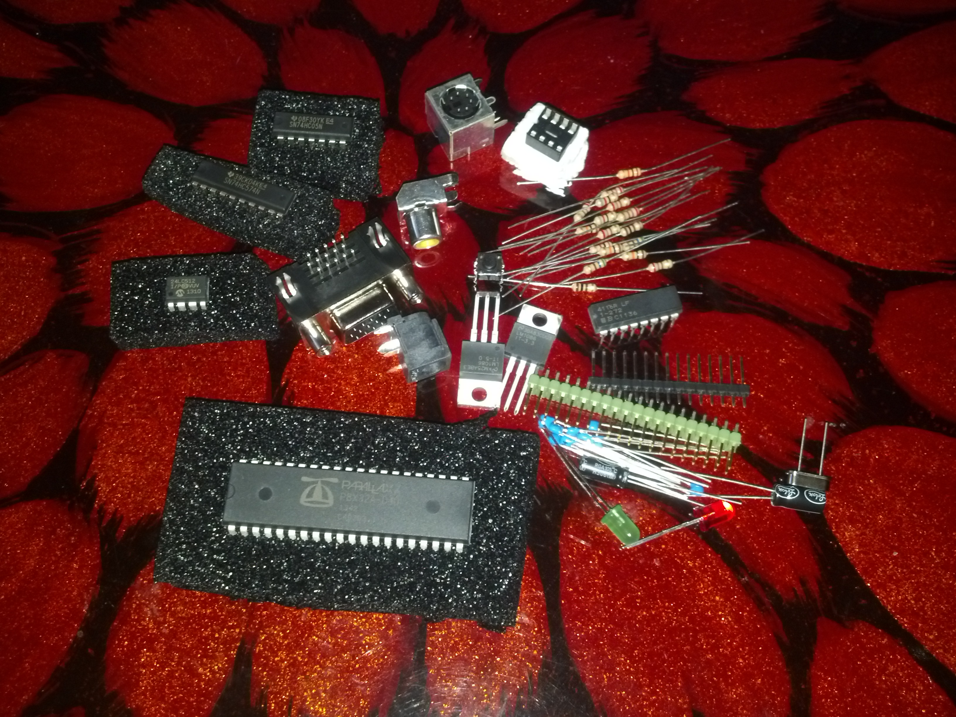
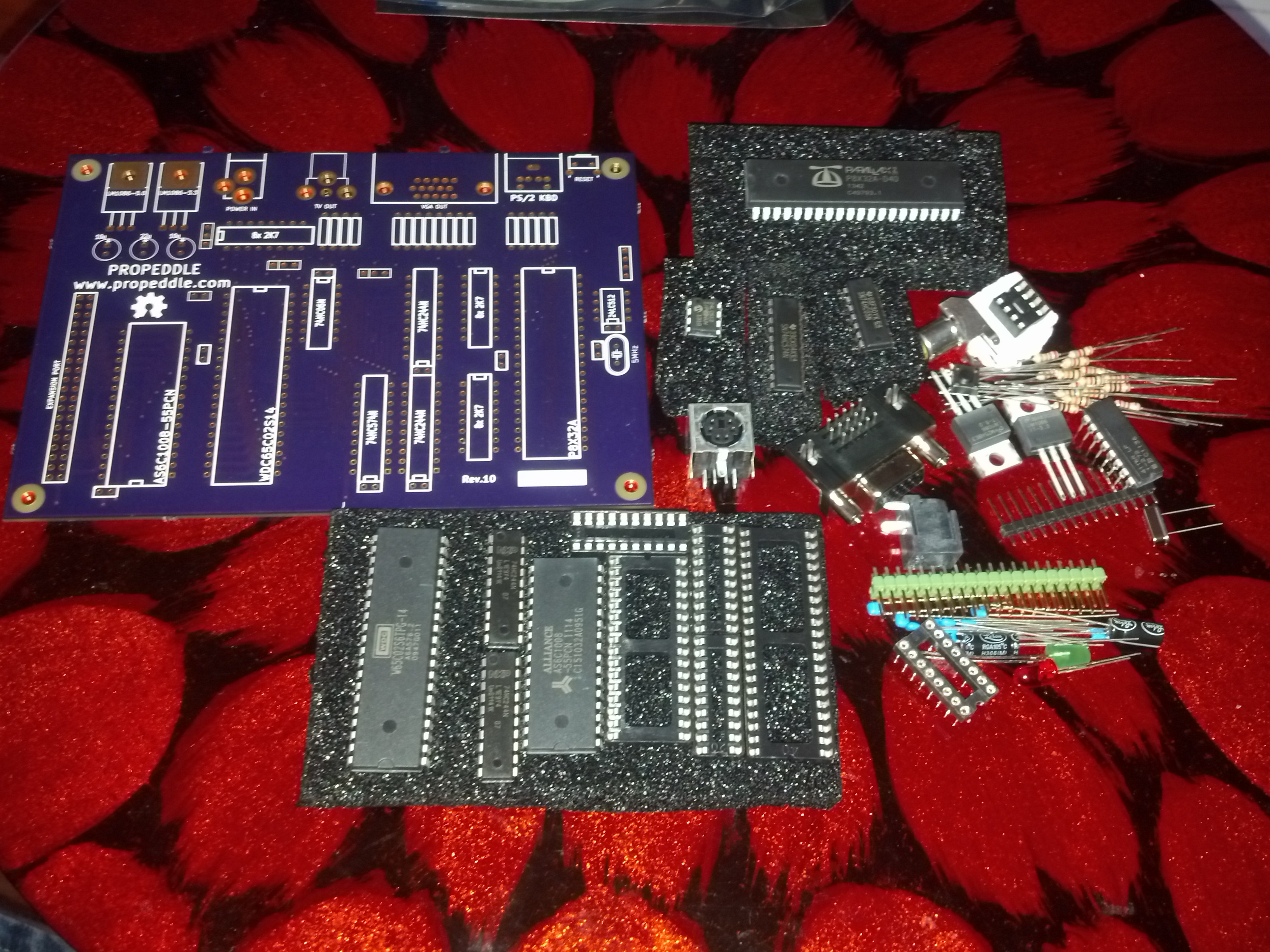
I put together a part list on Mouser for all the parts that are needed for a single Propeddle kit, but to save some money, I took off some of the parts that I still had in stock. So the photo above doesn’t contain everything you need. The photo below however, has everything on there.
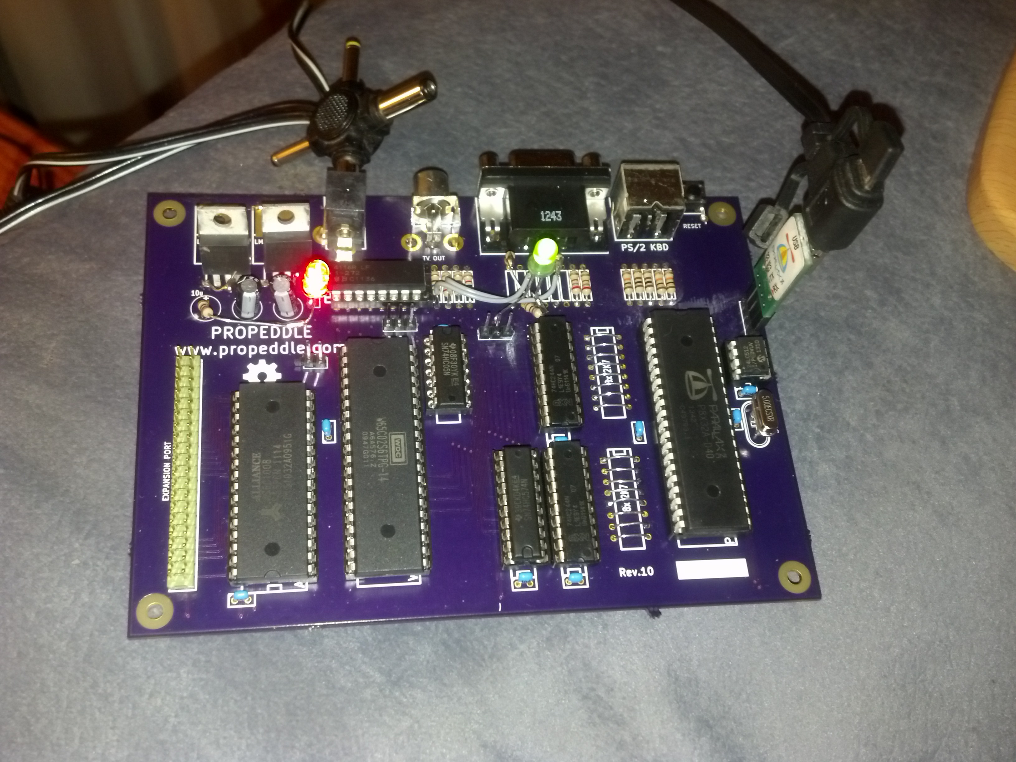
An hour or so later, I soldered all the parts on the board. Well, all the parts for which the Rev.10 board had space (not the LEDs, for example). I had to improvise with the PS/2 connector because it needs some more holes, but that was easy: I bent the side pins up, and bent the front pin around the circuit board. This was the result:
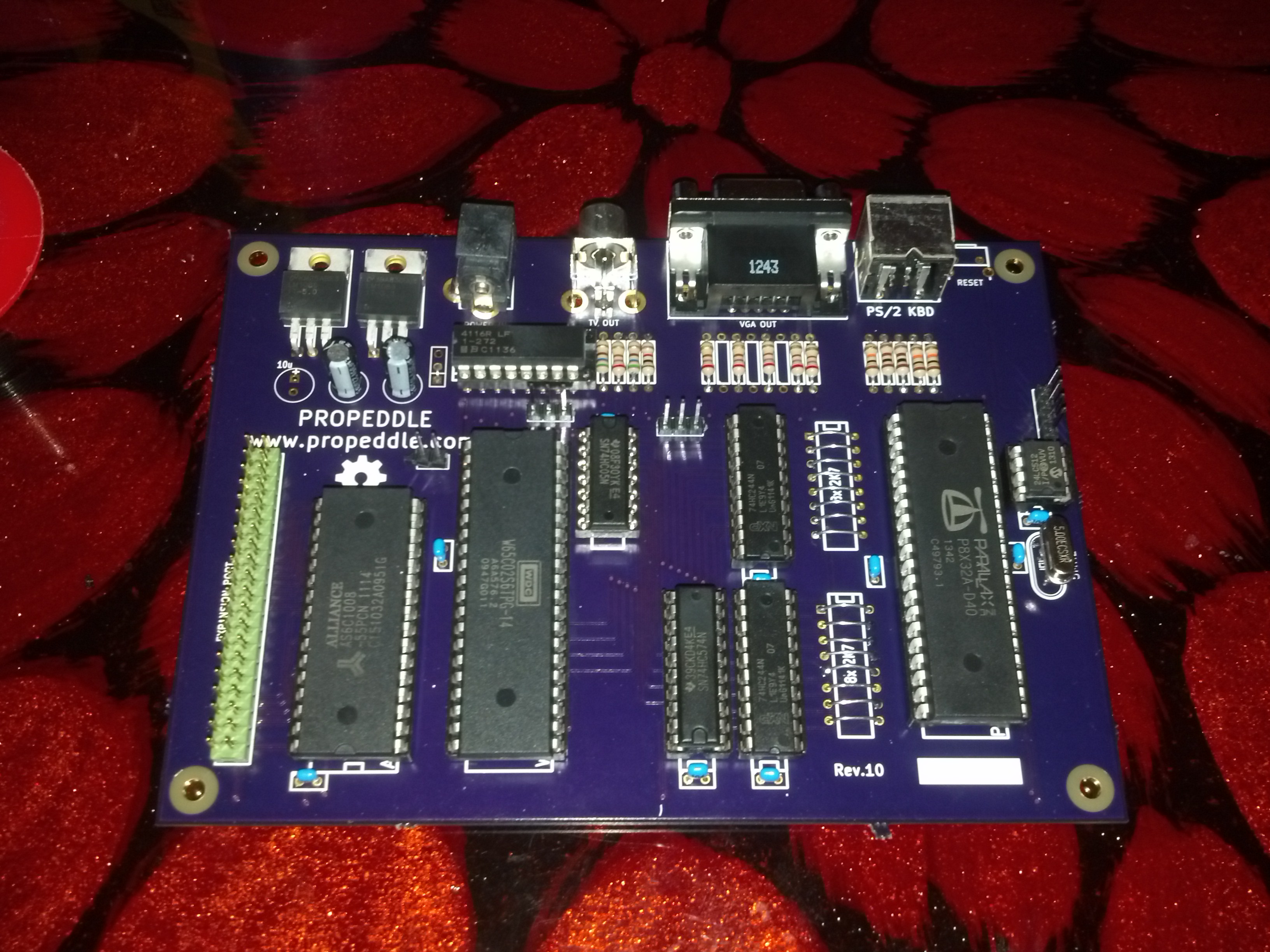
The wire bridges are there because the circuit is configured to run on 3.3V, so the resistors to lower the voltage from 5V to 3.3V aren’t needed. On the Rev.11 PCB I put trace jumpers on the bottom of the board, so that no bridges will be necessary. For most people this will work just fine: for most emulations and self-designed systems, the voltage doesn’t matter. But for those who want to use an original non-WDC 6502, the jumper traces can be cut, and the resistor packs (or regular resistors) can be installed. More information about this will eventually be in the documentation.
One capacitor near the power supply (top left) is missing: it didn’t show up in the shipment. Oh well, no big deal. The power brick I use, generates a pretty stable output, and with everything working at 3.3V and the Low Dropout Regulators (LDO) over-dimensioned at 1.5A, I don’t think anything bad will happen.
The missing resistors near the VGA connector are a design change that I implemented in the Rev.11 schematic. Normally a Propeller-based VGA output uses 2 Propeller pins per analog color output (red/green/blue). But because Propeddle doesn’t leave enough pins available on the Propeller for a full VGA output, I connected the resistors for the Least Significant Bits to ground. But for the same reason (pin availability), the TV video output is connected to the same pins as the VGA output; this is not a big deal as long as the unused output is left open so the impedance is determined only by the output that’s in use. However when there are resistors pulled to ground for the VGA output, it might influence the TV output. Without them, there should be no problem, though I need to change the values of the remaining VGA resistors slightly.
So all the parts were soldered and it looked pretty neat. Did it work? Ummm… no.
For some reason I must have not looked at the datasheet for the LDO’s long enough, because I designed the Kicad part with the pins switched around. Fortunately the “magic smoke” didn’t escape when I hooked up the power supply the wrong way, and the situation was remedied pretty easily with a piece of wire.
I also had to scrape off some solder mask and cut some traces on the PCB, and put some botch wires on the bottom because I moved some pins around between Rev.10 and Rev.11. I also added to two LEDs that I added for Rev.11 (one for power, one for debugging). The reset button was a similar story: Rev.10 had a right-angle button on the back of the PCB so it would be reachable from the outside of an enclosure, but I decided it would be more useful to have the serial port near the back of the PCB, so the reset button will move closer to the EEPROM chip on Rev.11, and will be a straight one, soldered onto the PCB. That may make it impossible to reach it when the board is inside an enclosure, but I’ll probably just add an extra 2-pin header so it’s possible to wire up a switch mounted anywhere in an enclosure. And of course, it’s also possible to reset the Propeller using the DTR or RTS line connected to the serial header.
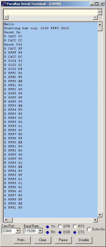
As I mentioned before, the Rev.8 Propeddle kit never worked at the full one Megahertz, even though all the chip timings and software timings should be within the limits in the data sheets. I’m still not sure why (it’s probably a subtle timing problem). The wire-wrap version did work at 1MHz, but the trace output seemed to drop some data. Today I found out that the problem was a parameter to one assembler instruction at the end of the Trace cog loop: I needed to let the loop wait for one less cycle to pick up the data bus value. When I wrote the code, possibly two years ago, I must have not realized that when an instruction copies the CNT (system timer counter), there is a one-cycle delay before it reads CNT, because the first cycle of the instruction is used to decode the instruction itself. Because of the off-by-one error, the main loop waited one cycle too long when the control cog was configured for an 80-clock loop, so the Trace cog would miss the deadline and would not read the next cycle correctly because the timing is so critical.
Which reminds me: I should rewrite the Theory of Operation page on this website…
===Jac