 (Note, some details of the drawing are out of date)
This article explains how the Propeddle electronics work in detail. Some generic knowledge of digital electronics, the Propeller and the 6502 are assumed, but even if you’re not familiar with the intricate details, you should still be able to follow this.
Overview
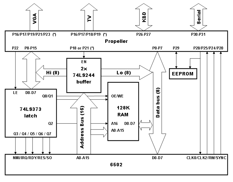
The Propeddle system consists of the following major parts:
- A 6502 processor
- A 128KB SRAM chip
- Some glue logic to connect the above to the Propeller
- The Propeller itself
- Peripherals such as a monitor and a keyboard
6502 Connections
You’re probably already familiar with the 6502 processor which has the following connections to the rest of the system:
- Clock: CLK0 (input), CLK1 and CLK2 (outputs). CLK1 is not connected.
- Control inputs: !RESET, RDY, !IRQ, !NMI, !SO.
- Control outputs: R/!W, SYNC.
- Address Bus outputs: A0..A15 (16 bits).
- Data Bus (input/output): D0..D7 (8 bits).
SRAM Connections
The 6502 uses 16 bits for its address bus, which makes it possible to access up to 64KB of memory. The Propeller only has 32K of hub RAM (plus 2KB per cog) so it’s not possible for the Propeller to provide all of this. This is why the Propeddle system has an AS6C1008 Static RAM chip which takes care of all the memory needs of the 6502, and then some: the chip has 128KB of capacity for practical reasons: 64KB SRAM chips are surprisingly difficult to find. These are its connections:
- Control inputs: !OE and !WR (!CE and CE2 are connected to GND and VCC so the chip is always enabled).
- Address Bus outputs: A0..A16 (17 bits).
- Data Bus (input/output): D0..D7 (8 bits).
Glue Logic
The Propeller is used to control the system but it also needs to be connected to peripherals such as a keyboard and a TV, and there are not enough pins to connect the Propeller to everything. For that reason, there are three chips on board that multiplex the Data Bus, the Address Bus and the Control signals for the 6502:
- Two 74HC244N octal bus drivers are used to connect the address bus of the 6502 to pins P0..P15 of the Propeller. The drivers are enabled by pin P24 (dubbed !AEN in the schematic).
- The !NMI, !IRQ, RDY, !RESET and !SO control inputs of the 6502, as well as the A16 address line of the SRAM chip, plus two spare outputs for future expansion are connected to the outputs of a 74HC374N octal D-type flip-flop. The inputs of that chip are connected to P8..P15 of the Propeller, and the flip-flop is clocked by P25 (dubbed SLC in the schematic). Obviously !AEN must be HIGH so that the logic levels from the address bus don’t interfere with the control signals sent to the flip-flop.
The Data Bus of the 6502 is connected directly to the Propeller on pins P0..P7. This is possible because during the first half of each 6502 clock pulse, the 6502 disconnects itself from the data bus. During that time it does generate an address, so the Propeller can use this time to find out which address the 6502 is trying to access.
Other Propeller Connections
For maximum efficiency, the R/!W output of the 6502 and the !OE and !WR outputs of the SRAM are connected directly to the Propeller on pins P23, P20 and P22 respectively. Pin P28 is used to generate the clock (CLK0) for the 6502.
Pins P16..P19 and P21 are reserved for audio and video. This may seem like a strange combination of pins: the standard for most Propeller designs is that P12..P15 are used for TV and P16-P23 are used for VGA. But P12 to P15 are needed for the address bus (if we would connect the address bus differently, it would take too much time to get its value during the very tight main loop in the Propeller software), and there aren’t enough pins available for a full 64-color VGA video generator. The pins were chosen so that a VGA port on the standard pins can be used with reduced colors, by masking off the least significant bits of the Red and Blue D/A converters. A TV output can be implemented by connecting the resistors to P16..P19 instead of P12..P15 and making a small change in the driver to use the different pin group. It’s even possible to use broadcast video this way.
Pins P26 and P27 can be used for a PS/2 keyboard, P28 and P29 are used for the EEPROM (P28 (SDC) is also used for CLK0) and P30 and P31 are used for the serial connection to a PC. All these are connected to their “standard” pins.
You must log in to post a comment.