After you use a script like Eagle2Kicad.ulp to export an Eagle design to Kicad, use the Kicad Library Editor to remove any symbols from the library that you created as power supply symbols. If you don’t, Kicad will be seriously confused.
I had a few symbols for VCC and GND in my Eagle design for Propeddle because I didn’t like the symbols that Eagle uses. This got me in trouble with Kicad, without it letting me know about it.
All I saw was lots of DRC errors in eeschema about power pins not being connected to anything. I tried to find out what was going on, and suspected that Eagle2Kicad had imported my power pins wrong: I had the power pins in a corner of my Eagle schematic, surrounded by decoupling capacitors, but in Kicad they were showing up as complete IC’s instead of just pins: the script had turned the power pins into separate units inside each IC, but had gotten the unit numbers wrong in the schematic, so the entire IC’s were showing up in the Kicad schematic where only the power pins should be.
I removed the IC’s to clean up the schematic because I wanted to fix some other problems first (for example, if you connect two signals to a bus in Kicad in the same location on the schematic, they are connected (shorted), whereas in Eagle, you can’t even connect multiple signals to each other because a net can only have one name; if you try to do it anyway, you’ll have to rename one of your nets.
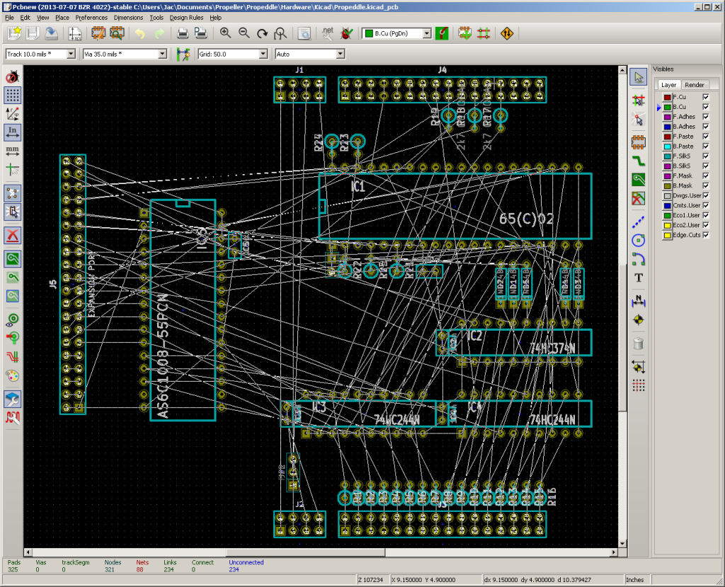
I read some information about how power pins should work in Kicad and found out that they’re usually implemented as invisible pins: they don’t show up in the schematic but all invisible pins with the same name are considered connected. I’m not sure whether I like the idea of hiding information like that, but there you have it, that’s how the Kicad engineers do it apparently. But when I tried to do the same, I couldn’t make it work. I kept getting DRC errors about power pins not being connected, and in my PCB design (which is still all rats nest) the power pins were showing up as non-connected. Also, when I added PWR_FLAG symbols to my schematic (which the tutorials said I should do to fix other DRC errors which I wasn’t getting), I started getting other errors saying I had connected multiple power outputs together.
Then after I made a simple schematic of a 7400 connected to a DB-9 connector, and compared the net list with my own net list, I discovered that while my .net file didn’t have a net for GND or VCC, it *did* have a *symbol* for those. I remembered that I had created those for the Eagle design, but I didn’t think of checking them; after all, I could hit P for “Add Power Symbol” and type VCC or GND to add them, and Kicad wasn’t complaining. So, more or less on a hunch, I decided to just delete the old VCC and GND symbols from the library that was generated by the Eagle2Kicad script (propeddle-cache.lib).
The schematic editor was now finding the power symbols in the power library instead of in my library, so nothing was lost in my schematic. I just had to add some wire because my symbols had been bigger than the standard ones that Kicad provides. But after I wired them all up and added the PWR_FLAG symbols as instructed, all DRC errors had gone and guess what: PcbNew was showing all the GND and VCC pins connected!

I decided that my short term goal for the Kicad project is to re-generate the PCB of Rev.8A of Propeddle, so that I can focus on learning Kicad, and so that I can make sure that all the little problems are solved and there are no mistakes. After that, I’ll clean it up so that it’s better readable: I want to use wires (not just labels) to show how signals are connected, but Kicad (unlike Eagle) doesn’t allow you to bundle signals into a bus unless they all start with the same name. It’s possible to draw a valid schematic with nothing but disjoint IC’s with a label on each pin (I know Vince Briel draws his schematics that way), but I’m “old school” in that I want to see where the connections are going. I prefer to use labels only when connections go off the page.
Later on, I’ll add additional schematic pages that will have the Propeller circuit, and another one with connectors (VGA, CVBS, Audio, power).
